OBD1 & OBD2
There are two types of vehicle diagnostic systems
They are: OBD1 & OBD2
* The Golden Rule:
(1) Always match the diagnostic tool with the diagnostic system in the car
(2) You can only use an OBD1 tool with an OBD1 system
(3) You can only use an OBD2 tool with an OBD2 system
Remember this simple rule & you will avoid unecessary problems at the start
It is a very common mistake to use the wrong tool for the diagnostic system in a car only to find the tool cannot connect to it. It is essential from the start to ensure the tool is compatible with the system in the car to be tested.
Many diagnostic tools are wrongly described as compatible with all cars from 1996 onwards. This is because all car diagnostic tools will normally link to all cars from 1996 in the USA but the same is not true of cars sold in Europe from that same year.
The modern On Board Diagnostic system was invented in the USA and routinely installed in all cars sold new in that country from 1996. The first stage of the OBD system is known as OBD1. The system was eventually adopted in Europe for petrol engine cars sold new from 2001 and for diesel engine cars sold new from 2004 when is was called OBD2. Commercial vehicles and 4x4 vehicles in Europe are commonly only OBD2 from 2008 year, most before that are still OBD1.
Most DIY diagnostic tools are only designed to link with OBD2 systems and cannot be used with OBD1. More expensive professional level tools will link with both OBD1 & OBD2 systems. It’s obviously very important to match the diagnostic tool with the OBD system in the car.
* OBD2 is usually written as OBD II
Is the car OBD1 or OBD2?
(1) Was the car made to be sold in America from 1996 onwards or is it a car that was imported into the USA from 1996?
(2) Is the car petrol and registered new from 2001 year for the European car market?
(3) Is the car diesel and registered new from 2004 year for the European car market?
(4) Has the car got a small D shaped 16 pin diagnostic socket located inside the car
If the answer to question (1) is yes, the car is OBD2
If the answer to Questions 2, 3 & 4 are yes, the car should be OBD2
If the answer is only yes to question (4) the car will normally be * OBD1
* Many Ford, cars are an exception to the normal rule. Ford put the OBD2 system into some Ford petrol engine cars sold in Europe from 1996 onwards but not in the the Escort model.
OBD2 Diagnostic Port
A few manufacturers put the OBD2 modern 16 pin diagnostic port into their cars early, before they changed the diagnostic system from OBD1 to OBD2 from the above dates. So just because the car has the modern 16 pin diagnostic port, it doesn’t mean the diagnostic system is OBD2. It will normally still be OBD1. If the diagnostic port is under the bonnet and not inside the car, the car is definitely OBD1
It’s often necessary with older cars to simply plug an OBD2 tool in to see if there is a link available from the car to determine if that car is OBD2. When a link error message is shown by the OBD2 tool it usually means the car is not OBD2
If the 16 pin OBD2 plug on the diagnostic tool doesn’t fit the diagnostic port inside the car, then the car is OBD1. Using an adapter cable with an OBD2 diagnostic tool would not help. An adapter cable cannot enable any tool that’s not designed for a system to connect to that system. An adapter cable can only be used with a tool that is designed to connect to both OBD1 & OBD2 systems
As already mentioned, the modern 16 pin diagnostic port was fitted in manufacturers cars several years before the change from OBD1 to OBD2 and therefore the 16 pin OBD2 port does not mean a car has OBD2 diagnostics
Where is the OBD2 socket?
It will always be located inside the car at the front, usually very close to the dashboard, often under or close to the steering wheel. It is meant to be discovered and to be accessed without requiring any tools to get to it.
Look carefully inside your car all around the dashboard area, around the fuse box inside the car, low under the steering wheel, behind the ashtray, by the handbrake, between the front seats and in the passenger and the driver’s foot well for the diagnostic socket. You may have to kneel down outside the car with the door open in order to see the diagnostic port if it’s situated above the foot pedals since they are frequently located there.
The diagnostic socket will always be fairly easy to get to, although it will often be hidden under a plastic trim cover to protect it from foreign objects and damage if it’s in the dashboard area. The small cover will normally be the same colour as the surrounding plastic trim and will easily hook off to reveal the diagnostic port.
Problems getting a link between the diagnostic tool and the car
Diagnostic tools are highly technical products. 100% compatibility with all cars is actually impossible due to the variety of diagnostic components in cars. No single diagnostic tool can link to all systems in all cars. A car may have an earth, a wiring, battery, damaged ecu, or other fault which can prevent a diagnostic tool linking. These problems may arise in older cars, salvage, stolen/recovered and damaged repaired cars.
A “link error” message from the tool usually indicates the tool is working properly but the tool is not suitable for the OBD system in the car.
TROUBLESHOOTING
Is the car OBD1 or OBD2?
Which system is the diagnostic tool designed to link to?
(1) Check the car ignition is switched on
(2) Check the diagnostic tool is turned on
(3) Check the lead from the diagnostic tool to the car is properly connected at both ends
(4) Check the car battery is fully charged to power the diagnostic tool with 12volts
(5) Check the plug on the tool is pushed very firmly all the way into the car diagnostic port
(6) Check the cigarette lighter fuse; it’s often shared with the diagnostic port
(7) Check the live feed to the diagnostic port at pin 16
(8) Check the earth in the diagnostic port at pins 4 & 5
(9) Try the diagnostic tool in another car to check the tool is not faulty
IMPORTANT: Despite the dates for the universal introduction of OBD2 in Europe, there are some 2001 petrol cars and some 2004 diesel cars that still do not have the OBD2 system. This is because those cars were made a long time, possibly a year or more, before they were actually sold and registered with plates. So be aware that a small number of cars fitted with the standard 16 pin OBD2 port and registered at a time when they should be OBD2 are not OBD2 because they were effectively old stock when first registered. They have the old OBD1 system in them.
Some things to consider when testing a car
A car must have12 volts car battery power (battery charged) for a diagnostic tool to connect. If the engine will not start, a tool won’t necessarily identify the reason and here's why. Modern cars diagnose their own faults and store the fault codes in their computer (ecu’s) memories. Diagnostic tools are not magic wands; on a basic level they simply read the ecu’s and show what is stored in them. When powered by a connection to the car, the tool sends a “wake-up” signal to the ecu and the ecu should automatically send its stored data back to the tool so it can be read.
The tool receives all data directly from the car and can only receive and display what is transmitted from the car. For that reason, if data transmitted from the car is confusing or meaningless, the fault lies with the diagnostics in the car and not with the tool.
When a car breaks down, the cause might be due to one of the engine components monitored by the cars diagnostics. With exception of emission controls, on board diagnostic monitoring varies between cars. Some cars have many components monitored whilst others don’t have very much, apart from the emission controls. Petrol cars can have more diagnostic components than diesels although in modern diesel cars there is now no difference. In fact modern diesels may have more.
When components in a car are monitored by the OBD2 system they are known as “supported” and they are “not supported” when the manufacturer has not included them in the car’s diagnostic system. Diagnostic tools can only read supported components in a car.
If the cause of the breakdown or non starting/poor running is due to the failure of one or more of the supported components then the car will normally store the information as fault code/s which can then be read with a diagnostic tool. If the cause is due to the failure of a component that is not monitored (not supported) by the cars OBD, (as with older cars) no fault code information will be stored in the car. In that situation it will be down to traditional investigation, fault tracing and a methodical process of elimination to establish the problem.
There are 5 protocols in the OBD2 system and a car will normally only use 1 of them
PROTOCOLS
J1850 PWM (pulse width modulation) used by Ford Motor Company and Mazda
J1850 VPW (variable width modulation) used by General Motors and in light trucks
ISO9141-2 = older protocol in Chrysler, European, and Asian vehicles between 2000-2004
ISO14230-4 KWP2000 (keyword protocol 2000) commonly used in cars from 2003
ISO 15765-4 CAN-BUS = first introduced in 2004 then mandatory in all vehicles from 2008
NOTE: There are 4 variations of CAN-BUS detailed below: each with different length and bus speed
(1) ISO 15765-4 CAN (11 bit ID,500 Kbaud)
(2) ISO 15765-4 CAN (29 bit ID,500 Kbaud)
(3) ISO 15765-4 CAN (11 bit ID,250 Kbaud)
(4) ISO 15765-4 CAN (29 bit ID,250 Kbaud)
The 16 pin diagnostic port normally utilizes only the pins required for the protocol in the car so it’s possible to guess the protocol with reasonable accuracy by looking at the pins used in the diagnostic port
VPW, metal contacts in pins 2, 4, 5, and 16, but not 10
ISO,metal contacts in pins 4, 5, 7, and 16. (15 may or may not be present)
PWM, metal contacts in pins 2, 4, 5, 10, and 16
CAN ,metal pins in 4, 5, 6, 14, and 16
Note:
ISO 9141 and ISO 14230 use the same pinout so you cannot tell the difference between them by just looking at the connector
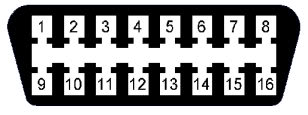
PIN USE IN NUMBERED ORDER
1 - Discretionary
2 - SAE-J1850 PWM and SAE 1850 VPW positive bus line
3 - Discretionary
4 - Chassis ground (battery negative)
5 - Signal ground (max 1.5 Amp)
6 - ISO-15765-4 CAN (high line) and SAE J2284
7 - K-line of ISO-9141-2 and ISO-14230-4 (data line)
8 - Discretionary
9 - Discretionary
10 - SAE-J1850 (PWM) (negative bus line) (not SAE 1850VPW)
11 – Discretionary
12 - Discretionary
13 - Discretionary
14 - ISO-15765-4 CAN (low line) and SAE J2284)
15 - L-line of ISO-9141-2 and ISO-14230-4
16 - Positive voltage (battery positive, max 4 amps)
Note: None of the 16 pins with the exception of (4) (5) (16) actually have any standard allocation therefore an ISO9141-2/ISO14230-4 car can use the SAE J1850 pins and vice versa. The only rule is that when different pin allocations are chosen they must not damage or confuse diagnostic compliant scan/test equipment
Note: Vehicle manufacturers can use the discretionary pins for anything they choose
HOW THE ON-BOARD DIAGNOSTIC SYSTEM WORKS
Modern vehicles diagnose their own faults. Various parts are monitored by the on-board diagnostic system via sensors and information is stored in the vehicle main engine control unit called the Powertrain
In older vehicles there are fewer electronic parts so less information is recorded in the vehicle. Airbags, ABS and other parts in older cars are often mechanical devices with no electronic controls. OBD2 in modern vehicles enables a wide range of information to be recorded.
The scope of diagnostic monitoring varies between vehicles. Apart from emissions components which are compulsory monitored in all vehicles, manufacturers can vary their choice of components monitored in the vehicles they make. Some cars have less diagnostic monitoring than others, purely for cost reasons, whilst others have on board diagnostic systems covering practically everything in 50 or more important components.
When a tool is connected for engine diagnostics, it links to the vehicle OBD system and shows engine performance and fault data stored as a diagnostic code. When no engine fault codes are found, it means there are no fault codes stored in the ecu but that doesn’t always mean there is no fault in the vehicle since a fault code can only be stored for a monitored component.
A monitor status of "N/A'' displayed by a diagnostic tool does not mean the tool is incompatible with the vehicle. It simply means that the test for that particular component or system is not applicable because the component is not monitored so it’s not possible to check it with a diagnostic tool.
DRIVING CONDITIONS BEFORE A DIAGNOSTIC TEST
A DRIVE CYCLE
This is any journey in which the engine temperature is raised from cold (below 49° C to normal operating temperature (above 71° C)
An OBD TRIP
This is a journey during which all OBD tests have been completed. For a full test it is important to ensure the vehicle is at operating temperature before scan testing and that the vehicle has been driven for at least 5 miles in different traffic conditions i.e. stop/start slow/fast and not just on a straight road and air con, electric windows, and all other electrical apparatus have been used. Ideally, the vehicle should be driven several drive cycles i.e. warmed up driven and allowed to get cold, warmed up driven and allowed to get cold - before testing, since some emissions related monitors will only give readings after several cycles.
A monitor status of 'Ready' on the scanner means that the driving conditions necessary to test relevant monitors have been met and the components tested have passed.
A monitor status of 'Not Ready' on the scanner means that the driving conditions for monitor testing have not been completed or alternatively, monitors have failed the test.
A monitor status of 'N/A' means that the vehicle OBD does not support the monitor/s to be scanned.
P1000 - MONITORS INCOMPLETE
Code P1000
After clearing fault codes or disconnecting the vehicle battery, the code P1000 is often found. This means that not all of the Monitors have been completed since they were cleared and this is not a fault condition. Once all of the OBD Monitors have been completed the P1000 code automatically clears itself.
MAIN MONITORS
I/M (Inspection & Maintenance) Monitors test the operation of emission-related systems or components and detect out-of-range values. There are currently eleven main I/M Monitors.
The I/M Monitors are:
*Misfire – *Fuel - *Comprehensive Components – *EGR/ Exhaust Gas Recirculation System
*O2 Sensor Oxygen Sensor -*A/T Catalyst -*Eva Sys/Evaporative System
*HO2 Sensor Heated Oxygen Sensor -*Secondary Air monitor - *Heated Cat Heated Catalyst
*A/C Referring Air Conditioning Refrigerant
ENGINE CONTROL UNIT
The Powertrain Control Module is a computer that can run up to eleven test programs (Monitors) that can run separately or in combinations under the direction of the OBD EXECUTIVE. Some monitors can run concurrently with others, some monitors are paused while others run, other monitors run all the time - and the Executive manages all these. When each monitor is run, the Executive stores the result of the test. In most cases the Executive will not light the MIL or store a fault code unless a monitor fails a test twice in successive OBD trips.
THE EXECUTIVE PCM
Diagnostic Trouble Codes are stored in the Powertrain Control Module also called the Main Engine Control Unit (computer)
Hardware devices connected to the PCM have their own device drivers, called Smart Drivers. These not only control the device by turning them on/off or controlling their duty cycle (a term for a variable device that opens and closes slowly by controlled degrees) but also tests the voltage and where applicable, the current drawn by the device. In this way connected hardware can be checked by the PCM without the use of secondary testing devices.
The following points are worth remembering because they have implications for trouble shooting.
WHAT THE EXECUTIVE DOES
It arranges the tests so that when a test runs, every input it relies on has already been tested.
Controls and coordinates the various tests (Monitors) i.e. MISFIRE, Comprehensive Component Monitor (CCM), FUEL,
CATALYST, EGR, HO2S, EVAP
Stores Freeze Frame data
Manages storage and erasure of Diagnostic Fault Codes and MIL illumination (where fitted.)
Controls and manages the On-Demand tests and Output Test Mode
Manages the transition from one test to another so as to minimize the effect on the vehicle operation.
Stores the results of the monitors. Clearing fault codes also clears the monitor results which results in code P1000
Interfaces between various monitor modes to provide diagnostic information and responds to special diagnostic requests.
Stores a fault code regardless of linked causes. Just one sensor problem can result in three or more different fault codes.
If the Executive cannot run a test it will not store a code for a failed component
If the reason for the failure to run the test is put right, the Executive will run the test during the next Drive Cycle and a new fault code will result. In this case, until it is put right, a failed component may mask another problem.
If the conditions for a monitor to run are not met in an OBD Trip then the test is not run and a problem will not be identified until the next OBD Trip. This explains why a fault condition may show itself several days after it was introduced.
Note:
The EXECUTIVE doesn't start monitoring until 4 seconds after the PDM is powered
OBD monoting is suspended if the battery voltage falls below 11 volts
3 CONTINUOUS MONITORS
These monitors run continuously while the vehicle is being driven:
MISFIRE
FUEL
COMPREHENSIVE COMPONENTS (CCM)
These three monitors are running all the time that the engine is running. The CCM is constantly checking the components to ensure they are working properly to provide test data for the other monitors. The Misfire Monitor is constantly protecting the Catalysts from damage caused by un- burnt fuel, while the Fuel Monitor is controlling the fuel mixture, switching it slightly lean and then slightly rich of Lambda (Closed Loop) and begins this 90 seconds after starting from cold.
NOTE:
Although the FUEL Monitor is running all the time this does not mean that the fuelling is in closed loop all of the time.
NON-CONTINUOUS MONITORS
The remaining monitors are run once in an OBD Cycle (a 'Trip'). The information on each monitor shows how long the test is run and what circumstances or criteria the test requires.
HOW FAULT CODES ARE GENERATED
The primary purpose of the OBD system is the control and reduction of pollutants: the two gases Carbon Monoxide (CO) and Nitrous Oxide (NOx), and un-burnt Hydrocarbons (HC). The The OBD system will sacrifice engine performance in order to control these substances within fine limits and to protect the catalyst(s) from damage.
The OBD switches the engine warning light (MIL) on when a failing component is detected or a component has stopped working. The warning light does not necessarily suggest a serious problem since anything that causes hydrocarbon emissions to exceed the legal limit by just 1.5 times will cause the light to switch on and there may be no difference in the way that the car drives. It is known that damp weather or just a loose fuel cap can be a cause for the engine warning light.
A misfire will cause the Check Engine light to flash while the misfire is occurring. A misfire in a cylinder will also set a P030? fault code. The last number in the code is the number of the cylinder misfiring. For example, a P0302 code would tell you cylinder number two is misfiring. The fault code alone does not tell you why the cylinder is misfiring therefore it’s necessary to investigate the cause. The misfire that is causing the code may be due to a dirty spark plug, a bad plug lead, a defective ignition coil in a DIS system, a clogged or dead fuel injector or a loss of compression due to a leaky exhaust valve, leaky head gasket or worn cam lobe.
OBD monitors the catalytic converter with a second oxygen sensor in the exhaust pipe behind the converter. By comparing upstream and downstream O2 sensor readings, OBD can detect the converter efficiency. If converter efficiency drops below the default setting, the OBD will turn on the engine warning light and store a fault code.
OBD can detect fuel vapor leaks (evaporative emissions) in the charcoal canister, evap plumbing or fuel tank by pressurizing or pulling a vacuum on the fuel system. If the fuel cap is loose or missing, it will detect it, turn on the engine warning light and store a fault code.
OBD can also generate fault codes for electronic transmission problems, air conditioning failures, such as a compressor failure, central locking, air bag, abs and many other components outside of the engine. Separate tools are often required to test and diagnose these other vehicle systems because most diagnostic tools are only for engine diagnostics.
WIRING & ELECTRICAL PARTS
OBD and the Comprehensive Components Monitor rely on hardware connections. If the engine wiring loom or wiring loom for the ecu or the component monitors are faulty, then misleading and confusing fault codes can be generated. Wiring looms may become damp which then corrodes the copper conductors and causes shorts. This may generate ghost signals which the Powertrain Control Module can interpret as out of range errors in components. When the engine warning light turns on because wiring or electrical components are damp the engine warning light may go out when the dampness dries out and there may be no codes stored. Alternatively, it may cause component fault codes to be stored in the ecu.
Wiring may be the cause of problems in the following cases:
Different fault codes which are non-connected codes for different sensors all at the same time
When the fault codes are erased they are replaced with different ones
Fault codes multiplying in wet weather or after the car is washed
Other symptoms: Battery draining overnight, O/D light flashing haphazardly and clearing, radiator fans running on, engine unexpectedly failing to start with good battery.
When these symptoms are present, the engine and wiring looms to ecu’s should be inspected carefully for signs of shorting. Remove covering tape from wiring and inspect the thin wall insulation for cracking, copper corrosion and shorting. The battery cover is there to protect the Auxiliary fuse box and relays from water ingress. If they become damp they can cause relays to energise at inappropriate times and permit water access to the ecu loom causing serious damage.
Finally, OBD can register and store thousands of “generic codes.” Generic codes have the same meaning in all vehicles and are compulsory in the OBD system but in addition, OBD can register and store manufacturers “enhanced” or “specific codes” which are unique to each of that manufacturer’s specific vehicles. These manufacturer’s codes are extra codes. Most diagnostic tools can show all generic codes and their definitions but it’s often necessary to Google manufacturer’s codes for a definition of them.
